
-
Solar panel single crystal converted into electrical energy
A solar cell, also known as a photovoltaic cell (PV cell), is an electronic device that converts the energy of light directly into electricity by using the photovoltaic effect. [1] It is a type of photoelectric cell, a device whose electrical characteristics (such as current, voltage, or. . Below is a summary of how a silicon solar module is made, recent advances in cell design, and the associated benefits. What is a Crystalline Silicon Solar Module? A solar module—what you have probably heard of as a solar panel—is made up of several small solar cells wired. . Perovskites made from lead halides are produced through low-cost solution processing and contain many defects. In a study published in Nature Communications. . Solar energy is converted into electricity through the photovoltaic effect, a process where sunlight, composed of photons, agitates electrons in a semiconductor material (like silicon) within solar panels. The unique. . A perovskite-based hybrid device developed by researchers at the Institute of Materials Science of Seville (ICMS) in Spain can operate simultaneously in rain and sunshine, overcoming the hurdles of using solar cells in cloudy conditions. The innovation is expected to boost deployments of the. .
[PDF Version]
-

Electrical system diagram of energy storage charging station
In this comprehensive guide, we will dissect the components of a battery energy storage system diagram, explore the differences between AC and DC coupling, and help you identify the right configuration for your commercial or residential needs. What is a Battery Energy . . Charging stations (electric vehicle supply equipment, or EVSE) are connected to Amazon Elastic Container Service (Amazon ECS)on AWS Fargate behind Network Load Balancer. AWS Lambda routes outbound open charge point protocol (OCPP) messages to EVSEs and Amazon DynamoDB keeps active connections. It is an informative resource that may help states, communities, and other stakeholders plan for EV infrastructure deployment, but it is not intended to be used. . The integration of EV charging supply equipment requires an integration of several high-power loads and an adaptation to the existing electrical infrastructure. This section presents basic principles for designing the EV charging infrastructure and its integration into the existing electrical. . At the heart of this understanding lies the battery energy storage system diagram—a visual roadmap that explains how energy flows, how safety is managed, and how power is converted. The station captures solar energy using photovoltaic (PV) panels and stores it in lithium-ion. .
[PDF Version]
-

Is the solar energy system the conversion of solar energy into electrical energy
Solar energy conversion describes technologies devoted to the transformation of solar energy to other (useful) forms of energy, including electricity, fuel, and heat. It covers light-harvesting technologies including traditional devices (PVs), emerging photovoltaics, generation via,, and related forms of directed at the generation of ener.
[PDF Version]
-

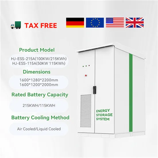
Electrical circuit of energy storage cabinet
The electrical integration design of a Battery Energy Storage System (BESS) is based on the application scenario and includes various aspects such as DC, high/low voltage distribution, control power distribution, grounding, lightning protection, and safety standards. . grid-compliant AC (alternating current). An [external] low voltage transformer fitted downstream feeds the AC (a ed in the on-grid mode and off-grid mode. The model with STS can get the faster sw net(PCS) is composed of 4 PCS-AC modules. The modules identify master-slave systems through the DIP. . If you're an energy systems designer, electrical engineer, or a renewable energy enthusiast trying to crack the code of efficient energy storage container circuits – welcome home. At HWOO, we provide energy storage battery cabinets built with reliable components that ensure safety, long. . Schematic diagram of capacitor energy storag r bank schematic diagram is illustrated in Fig. The bank consists of a capacitor bank of capacitance C s, a charging resistor Rc, a start switches S1, transmission line Tl, a crowbar switch S2, and a red value of the voltage across the capacitor. Helping to minimize energy costs, it delivers standard conformity, scalable configuration, and peace of mind in a fully self-contained solution. The battery system contains. .
[PDF Version]